How much energy does your choice of NTN antenna cost?
How much energy does your choice of NTN antenna cost?
We recently measured what a single satellite transmission actually costs compared to a terrestrial one, and showed that battery life is set far more by duty cycle than by the energy of each individual event.
But optimizing a wireless device for long runtime isn’t only about when it spends energy. Once the device is active, you want it to be as efficient as possible, wasting nothing. That’s where you turn to optimizing protocols and components — and one component stands out: the NTN antenna. One of the biggest levers you have.
Or is it? Let’s find out.
This is the fifth article in our series on power consumption with the Nordic nRF9151. If you want the full measurement setup, the waveforms, and the battery-life numbers behind what follows, start here:
- Measuring LTE Power Save Modes on Nordic nRF9151-DK
- Performance of LTE Power Save Modes on Nordic’s nRF9151-DK
- How much does NTN connectivity for IoT cost in energy?
- How much battery life does NTN actually drain?
Antenna theory: the polarisation
NTN differs from terrestrial in one respect that matters a lot. The signal from the satellite is either Right-Hand Circular Polarised or Left-Hand Circular Polarised, which means you need a circularly polarised NTN antenna to avoid unnecessary losses. With a linearly polarised antenna instead, you can lose up to 3 dB.
The problem with a circularly polarised antenna is that it is difficult to cover many different frequencies, and that is exactly why antennas for terrestrial connectivity are typically linearly polarised. So, a device that has to handle both terrestrial and NTN connectivity will normally end up with a linearly polarised antenna, unless two antennas are used.
The orbit matters too. GEO satellites are stationary, so if the device also has a fixed location, you can choose an antenna that minimises the losses in the link budget by optimising its direction, for example a directive patch antenna. If you are working with LEO satellites, or the device moves, another type of antenna is likely to be the better choice.
And then there is the distance. From our location in Lund, Sweden, the slant range to the GEO satellite is roughly 39,000 km, since the satellite sits 35,800 km above the equator and only about 30° above our southern horizon. Compared with a terrestrial base station a kilometre or two down the road, that is very far away, and every decibel in the link budget has to be paid for in energy.
The setup
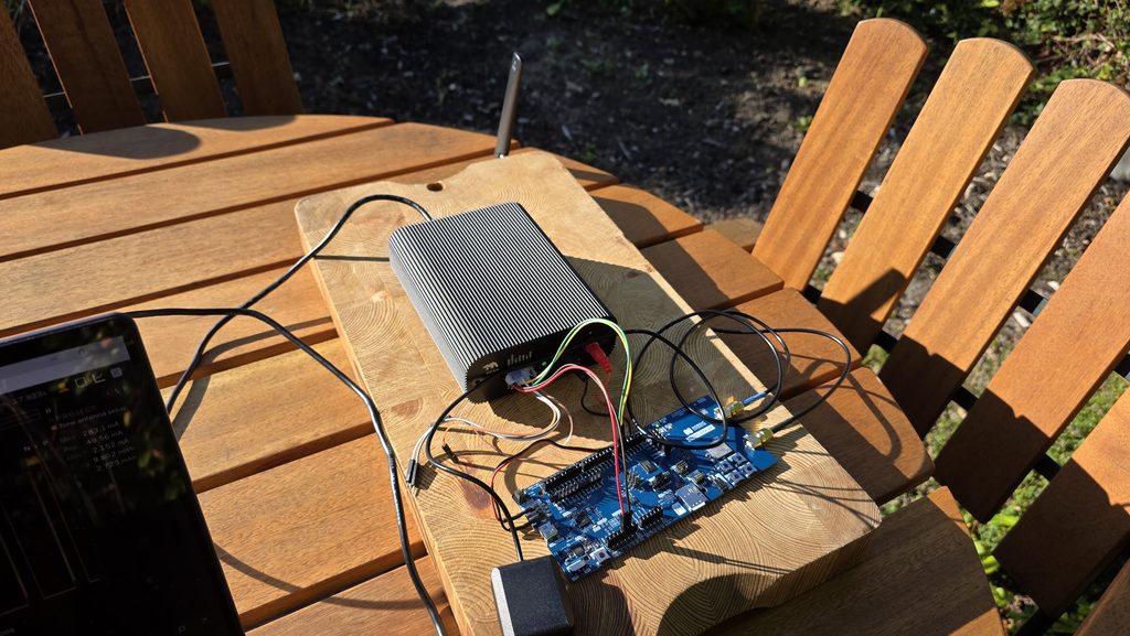
We are using the nRF9151-SMA DK from Nordic Semiconductor, communicating via Skylo GEO satellites using NB-IoT with a Monogoto SIM card.
The DK is connected in the same way as in the previous articles:
- The nRF9151 chipset is powered from the Otii Ace Pro main channel
- The rest of the DK is powered from the 0–15 V pin on the Otii Ace Pro
- UART communication with the nRF9151 goes via Otii Ace Pro UART RX and TX
- The GNSS and NTN antennas are connected to the dedicated SMA connectors
One practical detail: the NTN antennas are not connected directly to the DK’s SMA connector. One of them, the circularly polarised cap antenna, physically conflicts with the GNSS antenna connector and cable, so a 0.5 m SMA-SMA extension cable is used between the DK and the antenna. To keep the comparison fair, the same extension cable is used for every antenna, even where there is no conflict. Worth remembering when you look at the energy figures: a direct connection between antenna and DK would have given a somewhat better result for all of them, when that path loss is removed.
NTN antennas under test
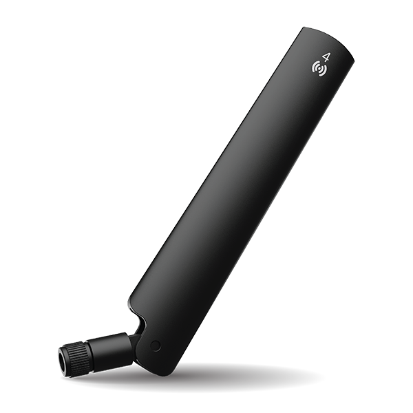
In this investigation we used a standard reference antenna included in the Nordics’ dev kit and couple of different NTN antennas provided by KYOCERA AVX.
- Reference antenna – miniature external antenna, the standard antenna included in the nRF9151-SMA DK package
- KYOCERA AVX X9003334 – external antenna (LTE-M/NB-IoT + NTN)
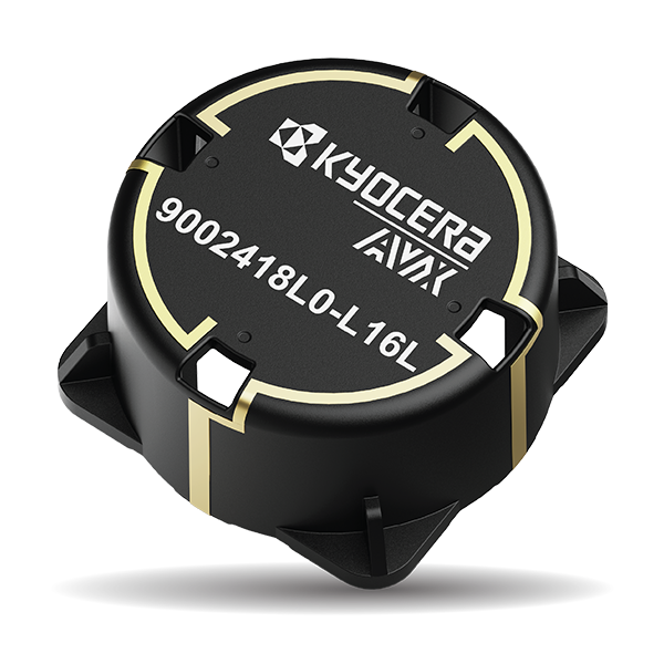
- KYOCERA AVX 9002418L0-L16L – circularly polarised L-band LDS cap antenna, tested on evaluation board
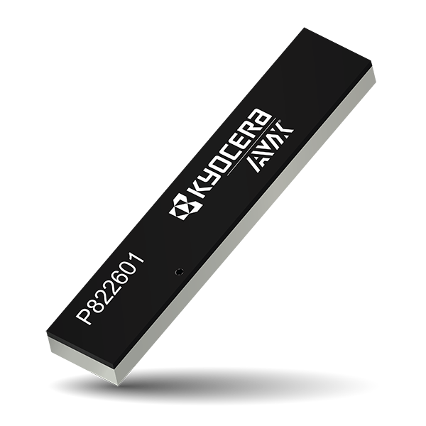
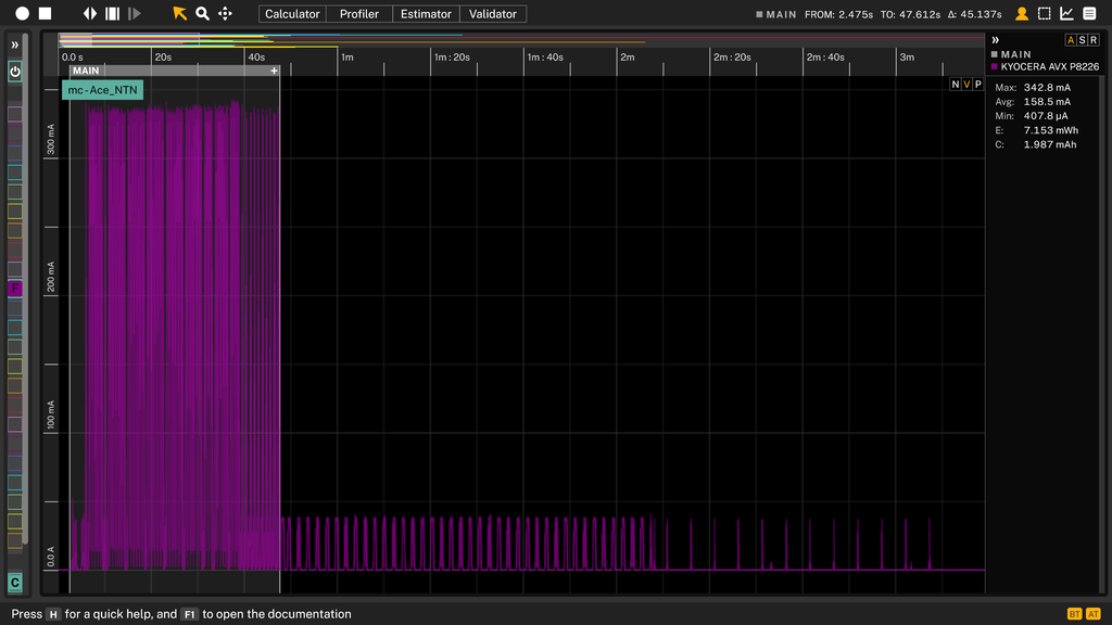
- KYOCERA AVX P822601 – embedded FR4 antenna (LTE-M/NB-IoT + NTN) matched for NTN, tested on evaluation board
The measurements and results
The measurement was done on the VDD_nRF rail of the nRF9151-SMA DK, powered with 3.6 V from an Otii Ace Pro.
The test was performed as follows:
- Power up the development kit
- Get a GNSS fix
- Set up and connect to the Skylo/GEO satellite using the Monogoto SIM
- Wait for the board to enter Power Save Mode (PSM)
- Transmit data and wait for PSM again
- Repeat the transmission to have three measurements
The test runs with the different antennas were performed directly after each other to minimise the effect of the environment as much as possible. Note that measurements are performed in a a live network, so there is a limit to how much we can control.
We are comparing the energy and charge for the data transfer part only, not the network registration part when it is set up and connected to the network.
To get a bigger difference between the antennas, a larger payload is used. In a real deployment this would typically be localisation data plus something like temperature or a health status, but for this test we send a 465-byte Lorem ipsum junk payload.
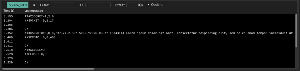
Current consumption with the reference antenna
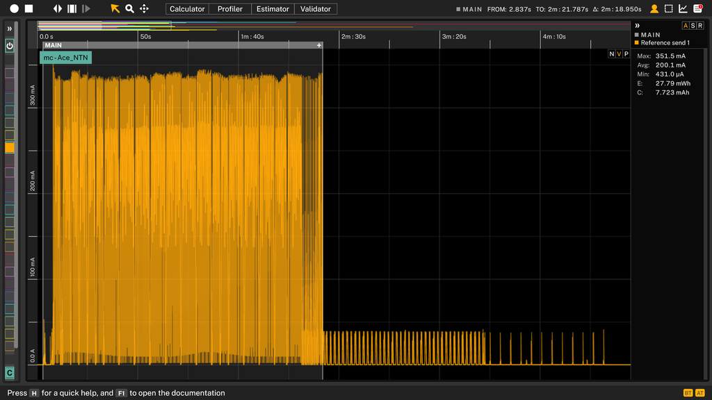
Current consumption with KYOCERA AVX X9003334
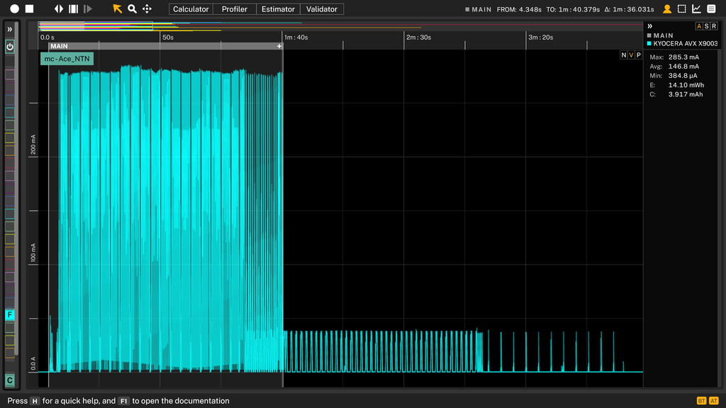
Current consumption with KYOCERA AVX 9002418L0-L16L
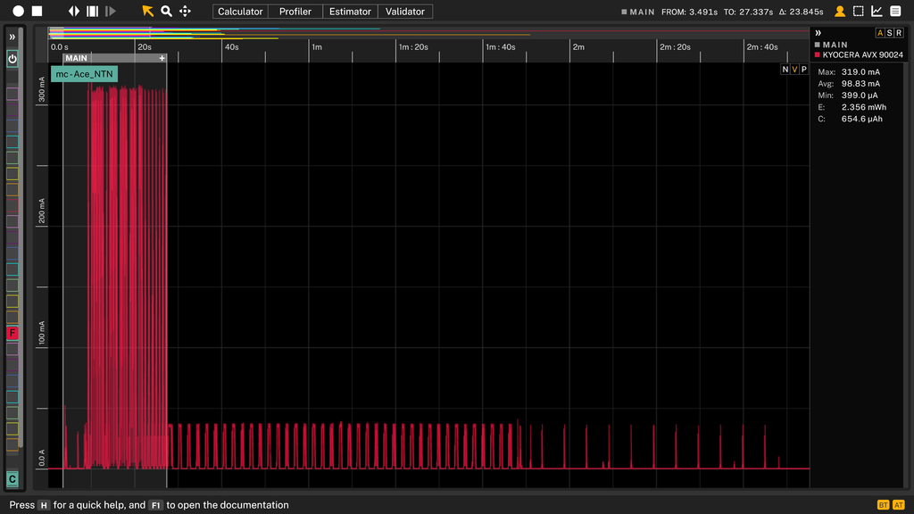
Current consumption with KYOCERA AVX P822601
Comparing energy consumption across NTN antenna scenarios
For a 465-byte data transfer, the comparison looks like this:
| Antenna | Energy (mWh) | Charge (mAh) | vs reference |
|---|---|---|---|
| Reference | 27.8 | 7.72 | 1× |
| KYOCERA AVX X9003334 | 14.1 | 3.92 | 2× lower |
| KYOCERA AVX 9002418L0-L16L | 2.36 | 0.65 | 12× lower |
| KYOCERA AVX P822601 | 7.15 | 1.99 | 4× lower |
The difference is clear. Best by a wide margin is the only circularly polarised antenna in the test, the 9002418L0-L16L, at nearly twelve times less energy than the reference antenna for the same payload. That said, it is not a candidate for a device that has to handle both terrestrial and NTN connectivity, unless a second antenna for terrestrial communication is added.
Second best is the P822601, which has an antenna matching circuit to improve coverage for both terrestrial and NTN connectivity.
Keep in mind that this is only the data transfer part of the communication with the satellite. On top of it come the GNSS fix, which is necessary for NTN, and the network registration. The payload is also larger than what you would normally transmit.
The NTN antenna changes the cost per event, not how often you pay it
In the previous article we landed on duty cycle as the design variable: the per-transmission cost is set by physics, and what you control is how often you pay it. The NTN antenna is the other side of that same equation. It does not change how often the device transmits, but it does change what each transmission costs, and by a factor that is in the same order as the 13–14× penalty we measured for going to satellite in the first place.
That makes it an unusually cheap optimisation. You are not trading away data or reporting frequency, and you are not touching the firmware. You are simply not throwing away decibels in the link budget, and every decibel you keep is energy the modem does not have to spend getting the same packet up to 39,000 km.
There is a caveat worth repeating: two of the antennas here were tested on their evaluation boards rather than integrated into a product, and all of them ran through the 0.5 m extension cable. In your own design the ground plane, the enclosure, and the placement will all move these numbers. The ranking is the useful output here, not the absolute values.
And as always, the numbers describe our antennas, on our bench, in a garden in Lund, on a live network we do not control. Measure your own device, in your own enclosure, and see where your energy actually goes.
[All measurements were made with the Otii Ace Pro. Board: nRF9151-SMA DK. Location: Lund, Sweden, outdoors with a clear southern sky view.]