Smart lab power supply for IoT and embedded devices
Smart lab power supply for IoT and embedded devices
When we embarked on the journey to bring the Otii solution to the market, we wanted to offer a comprehensive tool for measuring and optimizing device current consumption. We are happy to see how our customers use our products and fully leverage their multifaceted capabilities. One of the most straightforward yet highly valuable features of Otii Ace/Otii Arc is a really smart lab power supply. Essential for both hardware and software developers, a lab power supply is a fundamental tool in the day-to-day development of IoT and embedded electronics.
Programmable power supply
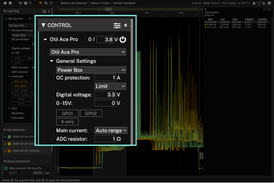
Despite their sleek appearance, Ace and Arc feature all the essential controls of a typical lab power supply, including voltage level and current limit controls. It is a digitally controlled power source that provides control over various settings, including variable voltage, current, power, and operating mode.
Unlike standard power supplies with front-panel controls, all adjustments and monitoring in Arc and Ace are performed via the Otii desktop app on your computer, supported on Windows, macOS, and Ubuntu. All of it can be automated by scripting in any language.
Power and measure simultaneously
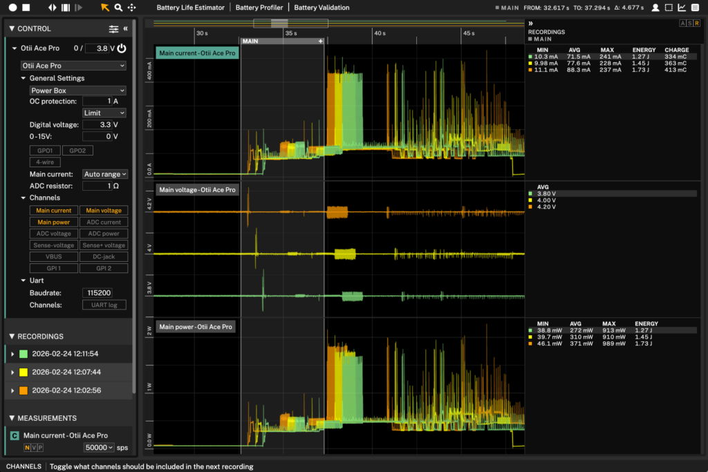
Otii combines a lab power supply, a current probe, and an oscilloscope. When testing a new device/module/chipset feature, monitoring the current to verify the circuit’s behavior is necessary. This is especially important when powering up the IoT or embedded device. Different parts of the device power up at different times. There are delays between various activities, and the software needs to boot up. Hence, it’s important to distinguish any anomalies in this process. Unexpected transients that would not have been visible on an ordinary current meter are easily spotted with Otii Arc/Ace. The current measurement’s high dynamic range (24 bits) makes even minor anomalies visible.
Additionally, thanks to the I/O interface, the logging of current, voltage, and other metrics allows the user to understand what draws current and affects the device’s battery life.
Otii Ace is an isolated power supply
In isolated power supplies, the input and output sides are electrically separated using transformers or optocouplers. This configuration offers several advantages over non-isolated power supplies but also comes with a higher cost.
The Otii Arc and Otii Ace power supplies differ in their power delivery capabilities and in whether they are isolated.
Otii Arc
The power supply of Otii Arc is not isolated, meaning that the low side of the power supply (main -) is connected to ground potential, which is the same potential as the USB port ground, DC plug ground, and the expansion port ground pins of Otii Arc.
Otii Ace
On the other hand, Otii Ace is an isolated power supply. It is isolated from the expansion port ground pins, the USB connector, and the DC plug ground.
Having an isolated power supply offers several benefits:
1. Ability to connect in series with another power supply
Otii Ace can handle up to a 200V difference between the power supply ground, the expansion port ground, and the USB/DC plug ground.
2. Avoidance of ground loops
Ground loops can introduce noise into measurements. Using an isolated power supply can minimize the impact of ground loops and improve measurement performance, especially in cases with 50 or 60Hz noise.
3. Safety
Although the voltages involved are low in the case of Otii Ac/Ace, having an isolated power supply adds an extra layer of safety.
When an isolated power supply comes in handy
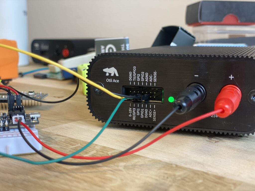
An example that illustrates the need for an isolated power supply is an IoT system that includes a fuel gauge connected to the low side of the battery, which may not be at the same potential as system ground. If the expansion port ground is connected to the device under test (e.g., UART or GPIO), it can cause a short circuit and incorrect fuel gauge measurements when using a non-isolated power supply.
However, with Otii Ace, which is isolated between the main, expansion port, and USB/DC plug, you would need to connect the expansion port digital ground (DGND) to use digital signals (UART and GPIO) and the expansion port analog ground (AGND) to utilize SENSE+, SENSE-, or ADC voltage.
Generating negative voltages is another valuable use case for isolated power supplies. By connecting two isolated power supplies in series and using the midpoint as a ground reference, a power supply can be created that provides both a negative and a positive voltage. This configuration is predominantly employed in applications that deal with audio signals or the development of analog electronics.
When the oscilloscope is not enough
Imagine a scenario in the early development stages of an IoT device, characterized by its miniature PCB and ultra-small components, where a critical issue arises during the power-down sequence.
Typically, one would solder small wires to ultra-tiny pads on the PCB, then monitor and capture the behavior with an oscilloscope.
Usually, it’s not possible to put a probe on the wanted signal when it travels from one BGA to another BGA well buried in a multilayer PCB. Monitoring current behavior with Otii Arc or Ace enables tracking the error. After correction, the correct behavior is easily verified using the same method. In this instance, with our customer, the exercise was used to compare against the original measurements, providing a visual reference for the development team to use in the future.
Summary
A lab power supply is not just a fundamental necessity in IoT and embedded electronics development. For hardware and software developers, choosing a programmable, isolated power supply offers unmatched versatility, enabling adaptation to various project needs. Moreover, selecting a supply that can simultaneously measure power consumption can be incredibly cost-effective, streamlining processes and reducing the need for multiple tools. The proper power supply can significantly enhance your development workflow, making it an investment worth considering for anyone in this dynamic field.
Do you have any questions on this topic? Contact us to learn more.