PFET for reverse voltage polarity protection
PFET for reverse voltage polarity protection
Choosing the right PFET as reverse polarity protection for a battery-driven device
Reversed polarity in a circuit can lead to severe consequences. Let’s assume your circuit is reversed, the positive wire is connected to the ground and the negative wire to the circuit’s power-supply pin. Or, you have reversed the polarity of a battery, maybe inserted an alkaline battery the wrong way. Two things could happen. Either the circuit, meaning all your hard work and components, gets burned, or the power source itself bursts into flames. Ok, this is probably a bit dramatic, but if your device is battery-driven, smoke and fire aren’t too far-fetched.
Protecting circuits from reverse polarity
There are several options to protect the circuit from reverse polarity. Most battery-operated devices use specialized battery connectors that prevent the battery from being connected in reverse order. This is a mechanical reverse polarity protection for the battery. Another reverse-polarity protection circuit solution that is becoming increasingly popular is the p-channel MOSFET (PFET).
PFET for reverse voltage protection
As a first step, selecting a PFET over an NFET is advisable, as it disconnects the positive rails of the batteries. Using NFETs and thus cutting off the negative rails would pose a risk of short circuits, electrocution, etc. Traditionally, a PFET typically had higher on-resistance than its NFET counterpart, but this is steadily improving. The on-resistance requirement is directly proportional to the device’s maximum current. However, when utilizing any FET with batteries, it’s crucial to consider a few factors; otherwise, it will perform worse than a Schottky diode.
As mentioned earlier, a battery, serving as a voltage source, is not a constant voltage source. Battery voltage is influenced by various factors, including:
- State of Charge (SoC)
- The amount of current that is discharged from the battery
- Temperature
So, if you are planning to use a PFET for reverse-polarity protection in your battery-powered device, consider some specs before making a decision.
Low voltage drop over the PFET is crucial
The lower the voltage drop, the better. The Rdson is only one part of the voltage drop, the other part is the diode voltage drop. You don’t want to reach the cut-off voltage for your load and sacrifice battery life.
To minimize voltage drop, your PFET must be operating at the correct voltage.
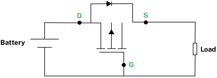
Figure 1 A simple example of PFET as reverse polarity protection
Reality check with a single alkaline cell
Consider the voltage at which your device is operating. For a single alkaline cell, the battery voltage typically ranges between 1.6V and 0.8V. Will your PFET function within this range? We have conducted tests to measure the PFET’s voltage drop for various Vgs voltages. It’s crucial to note that exceeding the PFET’s maximum Vgs rating could potentially damage the gate.
For this examination, we opted for the PFET SSM3J338R manufactured by Toshiba.
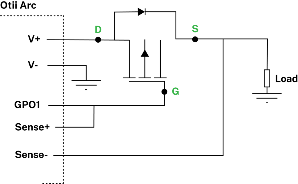
Figure 2 Otii Arc setup to investigate PFET voltage drop
Voltage investigation setup with Otii Arc
Using Otii Arc, we established a setup to investigate voltage drops across the PFET. The setup allows us to explore different battery voltages by adjusting the GPO1 pin voltage (Vgpo1).
Battery voltage in this case is V+ minus Vgpo1 and in this investigation, we have set V+ at 4V. The voltage the load sees is the battery voltage minus the PFET’s voltage drop.
V+ is the main voltage on Otii Arc. We can set Vgpo1 to any value between 1.2V and 5.0V, enabling investigation of the PFET voltage drop over battery voltages from 2.8V to 0V. The reason for not just changing V+ is that we – or you, when you do your testing – would like to have the same load situation. If we lowered V+, then we would also decrease the load current. By changing Vgpo1 instead, you keep the load current the same and the PFET does not see the difference.
Further, we used several different resistors as a load, ranging from 3 Ohms to 220 Ohms. In the recording below, you can see 3 ohms.
Also, try to avoid heating effects. We have paused for 60 seconds between each measurement to have the starting temperature roughly the same, and it turned out to be fine.
Results
So, our tests delivered the following:
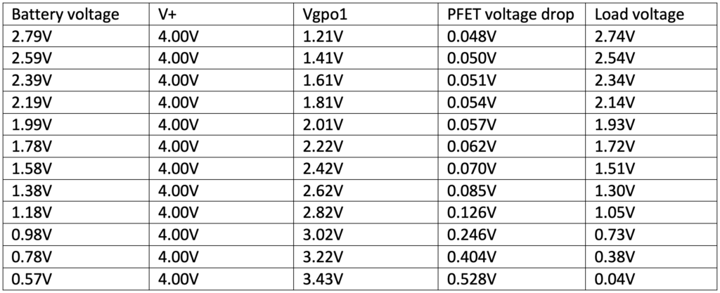
So, what does that mean? If we go back to the single alkaline battery used in our tests, you can see that for a battery voltage between 1.6V and 0.8V, our reverse polarity protection will cause a 70mV drop in voltage when the battery is new. However, the voltage drop will increase to 0.4V when the battery is discharged.
This is the point at which you need to check at what battery voltage your device will stop functioning, and whether that voltage drop is still acceptable. So, at the end of the day, you really want to make sure you use the right PFET for your intended battery voltage to avoid sacrificing your battery life. Needless to say, the voltage drop is only one of many parameters to consider when choosing the right PFET for reverse-polarity protection.
Want to know more?
Do you have any questions on this topic? Contact us to learn more.