
Ampere meter mode current
and power measurements of embedded devices

Ampere mode current and power measurements of embedded devices

Understanding the current consumption behavior of the embedded and IoT system while it is powered by the battery or energy harvesting such as solar panels, requires a setup where the measurements are in-line with the device and the energy source. This set-up enables ampere-meter type of measurements but can be extended to include energy as well.

In-line current and power measurements

This setup works with Otii Ace. Otii Ace acts like an ampere meter, connected via main connectors in line between the power source and the device under test (DUT). Positive current is current that flows out of the banana + connector. The power source in the setup can be any relevant source for embedded devices, for example, a battery or solar energy harvesting panel.

Note that in this setup you can choose to have only the current consumption measured or to also have voltage, power and energy measured. To measure additional voltage, power and energy the setup is extended with 4-wire connection using SENSE pins in the expansion ports of the Ace. 

Products needed

In-line current measurements
In-line current, voltage, power and energy measurements
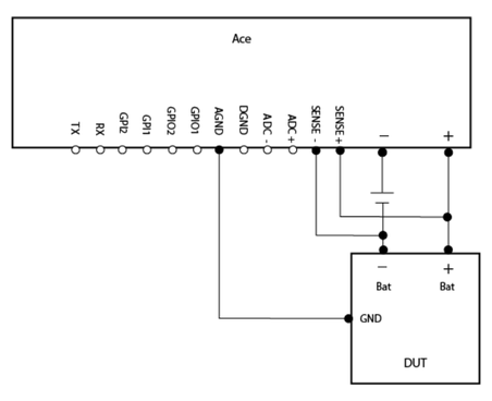
How to connect

  1. Connect Ace to your computer by USB.
  2. Connect Ace’s banana connector + to DUT’s positive battery connector/power connector.
  3. Connect Ace’s banana connector – to energy source positive pole.
  4. Connect DUT’s negative battery connector/power connector to energy source negative pole.

If you only want to measure current, you can proceed to the ‘Get started in the Otii app’. If current measurement alone is chosen, the voltage channel in the app, if enabled, will only display the voltage drop between banana connector + and banana connector -.

    If you also want to measure voltage, power and energy, then add this to the setup:

    1. Connect AGND to DUT’s GND
    2. Connect SENSE+ to DUT’s positive battery connector/power connector
    3. Connect SENSE- to DUT’s negative battery connector/power connector GND

    This setup with SENSE pins is called 4-wire and it provides the voltage measurements between the SENSE pins in the expansion ports, which is used to calculate power and energy.

    Get started in the Otii app

    1. Add your Ace under ‘Control’ in the sidebar. 
    2. Change from Power box to In-line mode in ‘General Settings’
    3. (Optional) Enable 4-wire button. This will highlight 4W next to the voltage control.
    4. Enable main current, (and if 4-wire enabled) main voltage and main power channel
    5. Start a recording
    6. Turn on Ace (Ace will not supply any power)

    Analyze the measurements! Here is how