Selecting the right supercapacitor for energy-harvesting BLE and LoRa applications
Selecting the right supercapacitor for energy-harvesting BLE and LoRa applications
Designing reliable energy-harvesting systems requires more than reading datasheets; it requires understanding how a supercapacitor behaves in real applications. To make informed design decisions, it’s important to combine theoretical knowledge with practical evaluation.
This article explains supercapacitors, electrostatic double-layer capacitors (EDLCs), and Lithium-Ion capacitors, their operating limits, and the PMIC’s role in energy-harvesting applications. The second part evaluates supercapacitor performance through real-world testing in BLE and LoRaWAN energy-harvesting systems.
Fundamentals of supercapacitor
Supercapacitor types
Supercapacitors with rated voltages of 2.5 V, 2.7 V, and 3.0 V are typically Electric Double-Layer Capacitors (EDLC). In contrast, 3.8 V supercapacitors are generally Lithium-Ion Capacitors (LIC).
LICs are hybrid supercapacitors that combine the characteristics of traditional EDLCs with elements of lithium-ion rechargeable batteries, offering a higher operating voltage while retaining many supercapacitor benefits.
Electrostatic double-layer capacitors
The rated voltage for EDLCs depends on the chosen material and manufacturing process. The higher the EDLC’s voltage rating, the more stringent the requirements on the manufacturing process. There are stricter requirements on the materials, including higher purity and lower moisture content. A higher voltage rating indicates a higher material purity and lower water content. There is also a difference in the electrolyte. In a 2.5V EDLC, the electrolyte can have a lower oxidation voltage than in a 3.0V EDLC.
A 2.5V EDLC has lower specifications and a lower price for the same capacitance as a 3.0V EDLC.
Lithium-ion capacitor
The electrolyte of LIC is more similar to that of a Lithium-Ion battery and can handle higher voltages than the electrolyte in an EDLC. This is needed to be compatible with the voltage of lithium intercalation.
Due to the lithium, LIC has a much higher energy density than EDLC, up to 4–5 times higher, but it also has some drawbacks. As with lithium-ion batteries, there is a minimum voltage threshold. For LIC, this is roughly 2.2V. If the LIC goes below this voltage, it will most likely be damaged.
This minimum-voltage limitation is absent in EDLCs.
Additionally, the cycle life differs between EDLCs and LICs. LIC has around 100,000 cycles, and EDLC typically has more than 500,000. Compared to a lithium-ion battery, these are very high numbers, as a lithium battery generally has only a few thousand cycles.
Temperature operating range
In terms of operating temperature, EDLCs have the widest range, typically –40°C to +85°C for 2.5V EDLCs. EDLCs with higher rated voltages typically have a slightly lower maximum temperature due to changes in the electrolyte solvent. Charging limits are also a little bit lower than discharging limits, as charging generates more internal heat in the super capacitor.
LIC has a somewhat narrower operating temperature range of –20°C to +60°C during charging and a wider range during discharging, but it is still far better than a Lithium-Ion battery.
How to select a supercapacitor?
Since supercapacitors differ in operating voltage and temperature ratings, these parameters are the first to be carefully considered when selecting a device for an energy-harvesting system.
Furthermore, the supercapacitor must integrate well with the system and, in particular, work well with the Power Management IC.
Power Management IC
The power brain of the energy-harvesting system is the Power Management IC (PMIC). This circuit controls the energy flow from the energy harvester to the storage and also from the storage to the application circuit.
In the PMIC, there are typically two or more DC/DC converters, including buck, boost, or buck-boost converters. The buck converter reduces the voltage level, the boost converter increases it, and the buck-boost converter can both decrease and increase it.
Generally speaking, the most power-efficient DC/DC converter is a buck converter, followed by a boost converter; the least power-efficient is a buck-boost converter.
In a typical energy-harvesting system, one DC/DC converter conditions the voltage from the energy harvester to charge the energy storage element, in this case, a supercapacitor. One or more additional DC/DC converters then regulate the voltage from the storage to supply the application circuitry.
Most commonly, the converter between the energy harvester and the storage operates as a boost converter, while the converter between the storage and the application circuit functions as a buck converter.
Why is this important?
If the DC/DC converter between the energy harvester and the storage is a boost converter, then the charging voltage level of the storage must, at all times, be higher than the voltage level generated by the energy harvester. This sets limits on energy harvesting, for example, the number of cells in a photovoltaic energy harvester that can be connected in series.
If it is a buck converter between the storage and the application circuit, the storage voltage must always be higher than the application circuit’s supply voltage.
The PMIC architecture, driven by the selected DC/DC converter, will constrain the choice of supercapacitor.
Great care must be taken across the PMIC’s operating conditions, especially regarding acceptable storage-voltage levels. Typically, the settings are the maximum voltage at which the storage stops charging, the minimum voltage at which charging is not allowed (so-called undervoltage), and the minimum voltage at which the application circuit is not powered to avoid undervoltage. These settings, together with the selected energy harvester and the voltage level required for the application circuit to operate normally, determine which supercapacitors are supported.
The PMIC datasheet typically also states the efficiency of the internal DC/DC converters. Also, great care must be taken to avoid selecting an inappropriate storage-voltage level based on the energy harvester’s output voltage and the desired output voltage of the application circuit. As much of the harvested energy as possible should be useful energy, not lost in inefficiencies.
PMIC examples
To give two examples of what to consider when selecting the right super capacitor, let’s start by looking briefly at the AEM15820 and AEM10330 PMICs from e-peas.
Example: e-peas AEM15820
This PMIC has a boost converter between the energy harvester and the storage, and a buck converter between the energy storage and the application circuit. This means that, with this PMIC, the energy storage should be selected to always remain above the energy harvester output voltage and the application circuit voltage.
The datasheet shows that the boost DC/DC converter between the energy harvester and the storage supports an input voltage range of 2.4 V to 4.59 V. This means that when the energy harvester charges the storage element, the charging voltage directly follows the storage voltage, so far, this behavior is as expected.
The buck DC/DC converter supplying the application circuit can be configured to output voltages between 0.6 V and 3.3 V. However, this output is constrained by the storage voltage and must always remain at least 250 mV below it.
As a result, when using a low-voltage supercapacitor, such as a 2.5 V EDLC, and targeting 1.8 V for the application, the usable supercapacitor voltage range is limited to approximately 2.1 V to 2.5 V due to the requirement of a buck regulator. Looking further into the configuration options reveals an additional limitation: the minimum storage-voltage threshold at which charging is still allowed is 2.4 V. This significantly reduces the supercapacitor’s usable energy window.
Taken together, these constraints indicate that the AEM15820 is not well-suited for low-voltage supercapacitors. It is better matched to higher-voltage storage elements, such as LIC supercapacitors or rechargeable batteries, which offer a larger usable voltage range.
Example: e-peas AEM10330
AEM10330, on the other hand, changes DC/DC configuration depending on the settings of the storage, and even though the setting is 1.8V for the application circuit and the storage is maximum 2.5V, it can utilize the energy of the storage down to 1.0V because it can be set to a buck-boost converter, accepting storage voltages above and below 1.8V. The drawback is lower DC/DC conversion efficiency at some voltages.
With AEM15820, a 2.5V supercapacitor would be terrible, but with AEM10330, it could be an option to consider.
Make sure you select a supercapacitor, an energy harvester, and a PMIC that integrate well.
Testing supercapacitors
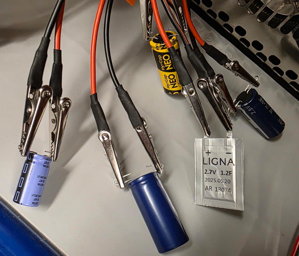
The test setup
To take a closer look at supercapacitors in energy-harvesting systems, we profiled a diverse selection of devices. The selection was intentionally broad to capture a wide range of characteristics rather than to enable direct comparison.
The chosen supercapacitors differ significantly in both design intent and specifications, with capacitance values ranging from 1.2 F to 100 F. As a result, this analysis should not be viewed as a side-by-side comparison, but rather as an exploration of how different supercapacitors behave in energy-harvesting applications.
We evaluated the capacity they can provide before the voltage drops below a specified threshold.
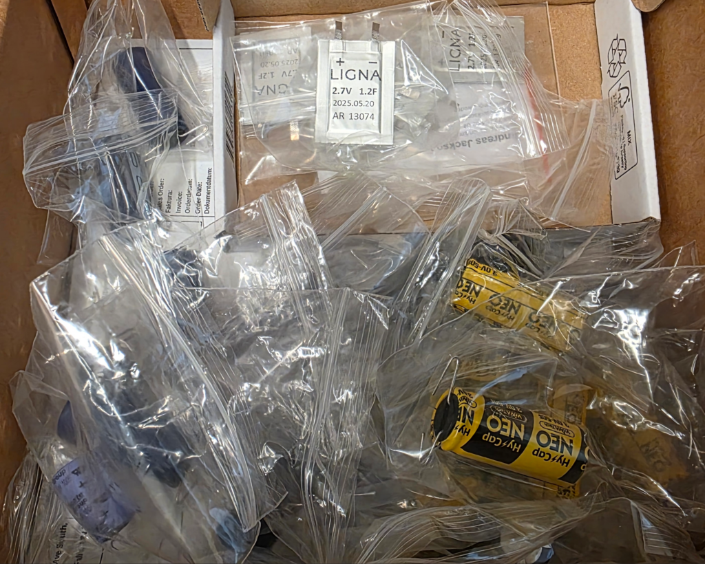
Five supercapacitors were selected for this study:
- 2.5V 60F Eaton HB1840‑2R5606‑R (EDLC)
- 2.7V 1.2F Ligna AR (EDLC)
- 2.7V 50F Abracon ADCR‑X02R7SA506M (EDLC)
- 3.0V 50F VINATech WEC3R0506QG (EDLC)
- 3.8V 100F Tecate Group TPLC‑3R8/100MR12X25 (LIC hybrid)
The capacitors have been power profiled with Otii Ace Pro and Otii Battery Toolbox using two different IoT discharge profiles, corresponding to a potential application:
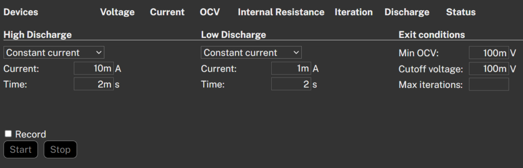
BLE sensor:
- High discharge: 10mA for 2ms
- Low discharge: 1mA for 2s
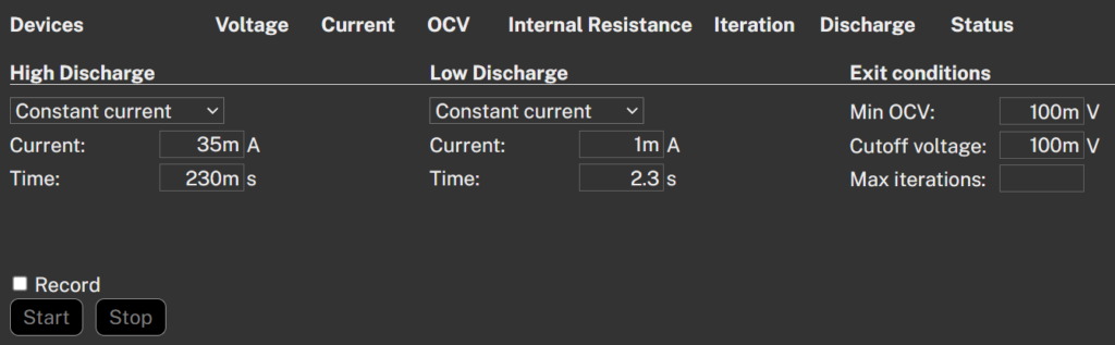
LoRa sensor, transmitting with spreading factor SF9:
- High discharge: 35mA for 230ms
- Low discharge: 1mA for 2.3s
All capacitors, except the Lithium-Ion capacitor, are discharged until there is no or very little energy left in them. The Lithium-Ion capacitor is discharged per the datasheet, stopping at 2.3V to avoid damage.
The profiling is performed in temperature chambers at the following temperatures:
- –10°C
- +25°C
- +60°C
The results
The result is not surprising.
The supercapacitor voltage decreases linearly as energy is discharged, and the internal resistance is very low, typically below 100 mΩ.
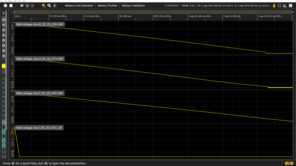
Figure 5, above, shows the EDLC voltage during discharge under the BLE profile at 25 °C. As expected, the 1.2 F supercapacitor from Ligna (fourth trace in the graph) exhibits the shortest discharge time, while the 3.0 V supercapacitor (third trace) maintains operation the longest among the devices shown.
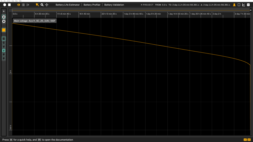
The LIC has a similar behaviour except at the end of the discharge, where it gets close to the undervoltage limit, and it deviates from the linear behaviour. Also, we weren’t surprised that this one lasted even longer than the 3.0V EDLC (VINATech).
If we compare supercapacitor performance using the same approach typically applied to batteries, expressed in mAh, it looks like this:
Overall, the measurements show that EDLC capacity is generally not significantly affected by temperature, whereas LIC capacity is noticeably affected. Ensure that you take this into consideration when designing your device.
The small variations observed in the measurements are likely due to differences between individual capacitors, as each test was performed on a different physical device rather than repeated measurements on the same capacitor.
When comparing the two communication technologies, BLE and LoRa, for each supercapacitor, only minor differences are observed for EDLCs, while the impact is more pronounced for LICs.
Each LoRa transmission draws more energy per pulse and exhibits a higher peak current than BLE. For LICs, the discharge is constrained by a defined minimum voltage, and the higher peak currents affect the voltage drop caused by the capacitor’s internal resistance. As a result, the usable discharge ends earlier. In contrast, EDLCs are discharged until nearly all stored energy is depleted, which helps explain why the difference between BLE and LoRa is minimal for EDLCs but noticeable for LICs.
This highlights an important point: the usable capacity of a supercapacitor is determined not only by the capacitor itself, but also by the PMIC’s minimum storage voltage.
Measurements like those presented in this article make it possible to determine how much of a supercapacitor’s nominal capacity a given PMIC can actually utilize in a real application.
Summary
Selecting a supercapacitor for energy harvesting requires matching it to the PMIC architecture. The DC/DC converters and their voltage thresholds ultimately determine the amount of stored energy available for use. EDLCs offer a wide operating temperature range and no strict minimum voltage limit. LICs, on the other hand, provide higher energy density but come with tighter voltage constraints and greater temperature sensitivity.
Building on this foundation, the practical section of this article examines how these differences manifest in real-world operations. We profiled several supercapacitors with widely varying characteristics using realistic IoT discharge patterns for BLE and LoRa devices at different temperatures. The measurements confirm the expected behavior: EDLCs discharge linearly and show little sensitivity to temperature or discharge profile, while LICs exhibit greater variation and are constrained by their minimum operating voltage. The results also show that the usable capacity depends strongly on the lowest voltage the PMIC can support, not just on the capacitor’s nominal rating. Testing under realistic discharge conditions clarifies the amount of energy a specific PMIC–supercapacitor combination can deliver to an application.