ESP32-S3 Deep Sleep Power: vs C3 vs C6, Measured
ESP32-S3 Deep Sleep Power: vs C3 vs C6, Measured
Every battery-powered device has a power floor — the current it draws when it’s doing nothing at all. No active radio, no sensor reads, no application logic, just the board sitting in its deepest sleep mode. That floor sets the lower bound on battery life, and it’s one of the numbers a datasheet states most confidently: sleep current is right there in the electrical characteristics table, quoted to the microamp.
This series starts there, at the floor, with three ESP32-family boards on the bench — the dual-core Xtensa ESP32-S3, the RISC-V ESP32-C3, and the 802.15.4-capable ESP32-C6. They aren’t interchangeable parts; different cores, different memory, different radios. But that’s not what we’re testing here. We’re testing one thing: how much current each board actually draws in its deepest sleep, measured against the others and against the number its own datasheet promises.
Because that datasheet figure is a starting point, not an answer. It’s captured under specific conditions, often on a bare chip, that rarely match the module sitting on your desk — and “deep sleep” can mean several different states depending on what you leave powered. Before you layer BLE, Wi-Fi, or Thread on top — which we’ll do in the articles that follow — it’s worth knowing whether the quiet baseline underneath them is where the datasheet says it is.
What the datasheets say for the three ESP32 boards
There are two sets of numbers for each board, and they show different things.
Espressif’s SoC datasheets give bare silicon measurements at 3.3 V, 25 °C, with no external components. These set the theoretical floor.
| ESP32-S3 | ESP32-C3 | ESP32-C6 | |
|---|---|---|---|
| Modem-sleep | 27.6 mA | 16 mA | 17 mA |
| Light-sleep | 240 µA | 130 µA | 180 µA |
| Deep-sleep | 7 µA | 5 µA | 7 µA |
Modem-sleep values as published in the Espressif datasheets. These correspond to the CPU idle condition. Espressif lists multiple sub-conditions, CPU running vs idle, peripheral clocks on vs off. This validation used the WAITI (CPU idle) state at 160 MHz.
Seeed Studio’s board-level documentation includes the contributions from all onboard components (LDO, battery management, USB bridge, external flash).
| XIAO ESP32-S3 | XIAO ESP32-C3 | XIAO ESP32-C6 | |
|---|---|---|---|
| Modem-sleep | 27 mA | 25 mA | 30 mA |
| Light-sleep | 2 mA | 4 mA | 3.1 mA |
| Deep-sleep | 14 µA | 44 µA | 15 µA |
Note: the Seeed light-sleep values assume an active WiFi connection. The implications of this are examined in detail below.
No single table can show exactly how much power your device will use in the actual conditions. Actual power consumption depends on how the hardware, firmware, and application work together. While datasheets are useful for checking your design, real measurements are what matter most if you care about device lifespan.
Setting up a reproducible baseline
We measured all three boards using an Otii Ace Pro power analyzer (50 ksps, 0.4 nA resolution) connected to the VBAT pins on each development board.
The supply voltage was set to 3.8 V using the battery pad. Espressif’s datasheet values are based on 3.3 V applied directly to the chip, but XIAO boards include an onboard LDO between the battery input and the chip, which requires a voltage above 3.3 V to keep the regulator within its proper operating range.
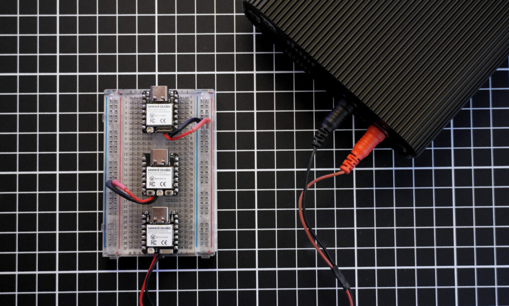
The test firmware was compiled using ESP-IDF 5.5.3 via PlatformIO. Each board ran the same state-machine sequence: a 10-second LED blink preamble followed by 15 seconds in modem-sleep, 15 seconds in light-sleep, and 15 seconds in deep-sleep. No peripherals were initialized beyond a single GPIO for the LED.
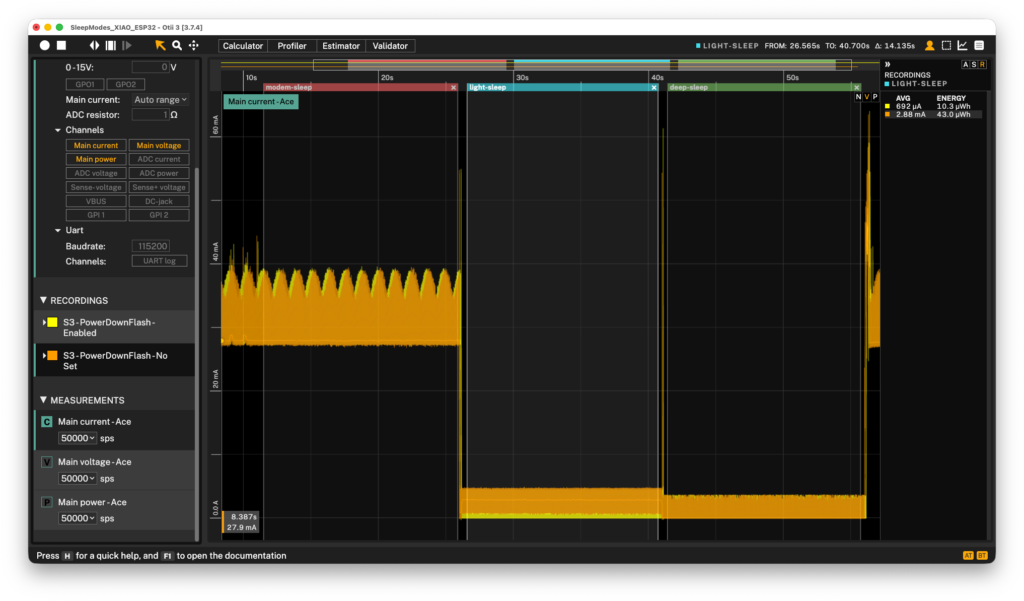
In the first round of measurements, the S3 showed a light-sleep current of 2.88 mA, as shown by the yellow graph in the image below. This matched the Seeed board-level spec but was much higher than the SoC datasheet value of 240 µA. The difference came from the external SPI flash memory. By default, ESP-IDF keeps the external flash rail powered during light-sleep. While the SoC core enters low-power mode, the SPI bus pins are not isolated, which causes cross-pin leakage or keeps the flash IC in active standby, using an extra 1.5 mA to 2.5 mA.
Setting the firmware-driven hardware power-gating via CONFIG_ESP_SLEEP_POWER_DOWN_FLASH=y forces the regulator to cut power (VDD_SPI) to the flash chip during the sleep transition. This single-line optimization dropped the ESP32-S3 light-sleep current from 2.88 mA to 692 µA, yielding a 76% power reduction.
Unlike the S3, the RISC-V-based ESP32-C3 and ESP32-C6 showed almost no change with the hard power-down setting. The C3 current dropped from 204 µA to 193 µA, and the C6 dropped from 233 µA to 220 µA.
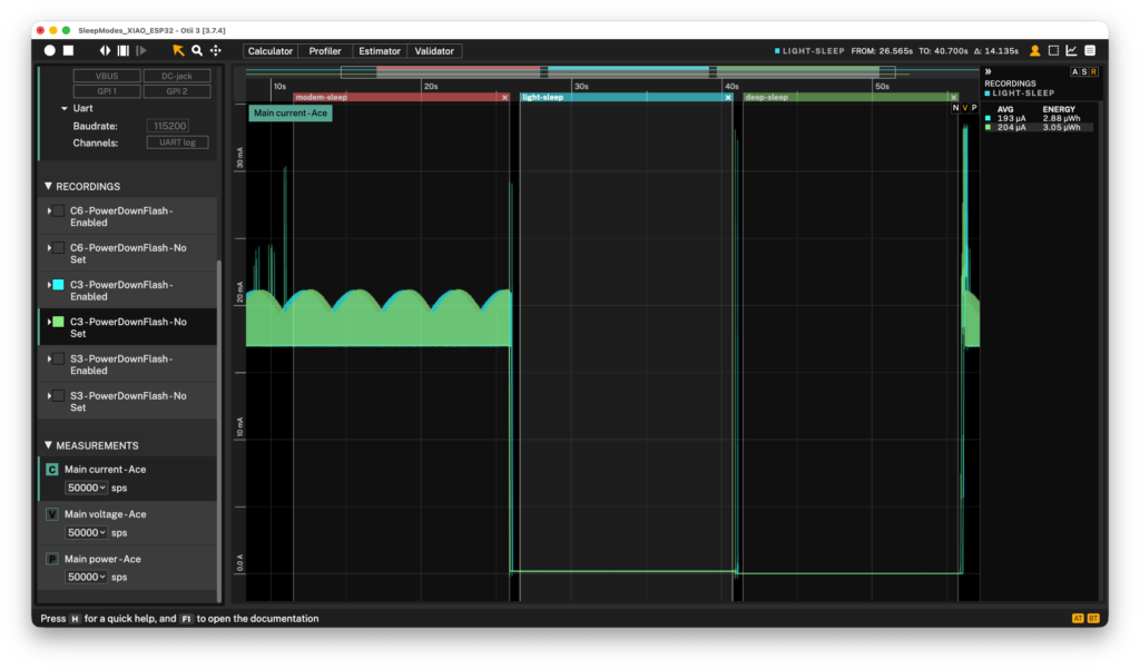
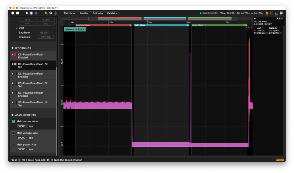
Measurement overview for XIAO ESP32-S3, ESP32-C3, and ESP32-C6 boards:
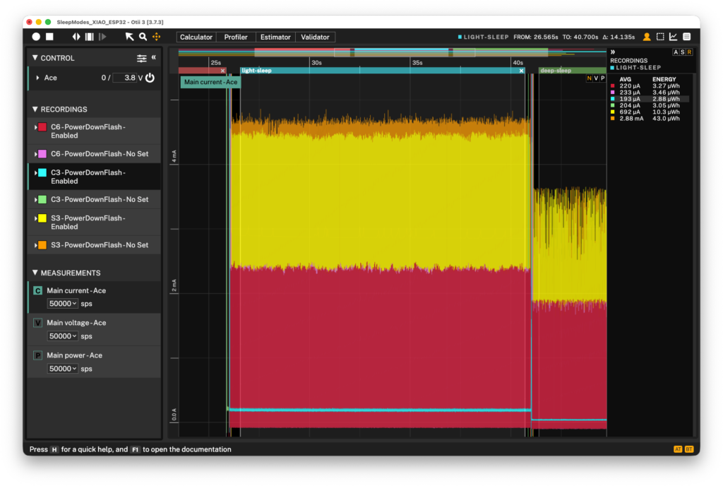
The power savings here are small because the default software-managed pin isolation on these chips already removes most leakage. Only 11–13 µA of standby current remains to be saved. This is different from the ESP32-S3, where the same setting fixes a major hardware pin-leakage path and causes a much larger drop in power consumption.
These results show that low-power optimizations work differently on each chip architecture. A big fix for one SoC might only give a small improvement on another. Still, it is good practice to enable the optimization for all boards.
ESP32-S3, C3, and C6 measured
With each board running the same sequence, conditions, and power supplied at 3.8 V through the battery pins, the table below lists the final validated measurements.
| XIAO ESP32-S3 | XIAO ESP32-C3 | XIAO ESP32-C6 | |
|---|---|---|---|
| Modem-sleep | 28.1 mA | 17.0 mA | 19 mA |
| Light-sleep | 692 µA | 193 µA | 220 µA |
| Deep-sleep | 13.4 µA | 41.6 µA | 16.9 µA |
Modem-sleep measured at 160 MHz, CPU idle (WAITI). No radio stack initialized. 15-second hold per phase.
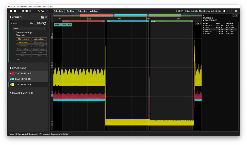
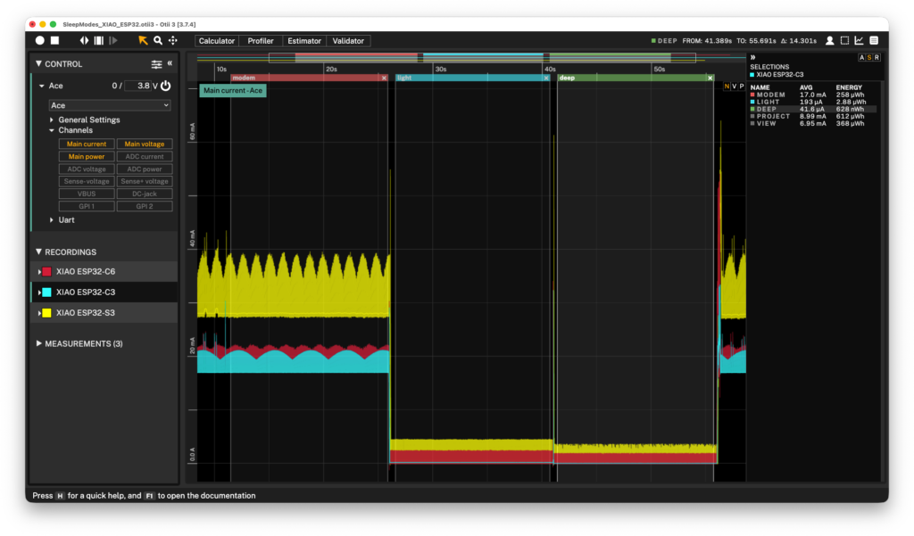
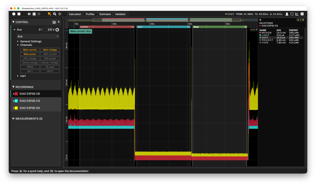
Several of these results sit in a different place than either datasheet predicts. The following sections break down where and why.
Where the numbers diverge
Light-sleep: the gap between board spec and measurement
Seeed’s board-level specs list light-sleep current as 2 mA (S3), 4 mA (C3), and 3.1 mA (C6). The validated measurements came in at 692 µA, 193 µA, and 220 µA; between 3× and 21× lower.
The difference is due to the radio. Seeed’s figures assume the device maintains its WiFi connection during sleep, so the RF front-end wakes up periodically to check for the access point’s DTIM beacon. In this test, the radio stack was not initialized. The measured current only covers SRAM retention and board overhead, which matches what you get if your battery-powered design turns off the radio before sleeping. Using the Seeed light-sleep spec to size a battery for a radio-off design would overestimate the light-sleep current contribution by 4 to 21×, depending on the board.
Among the three boards, the S3 reads 3.5× higher than the C3 and C6. This is architectural: the ESP32-S3 has 512 KB of SRAM split into several retention domains, and each one draws current during light-sleep. The C3 and C6 have less SRAM and fewer domains. If your design spends a lot of time in light-sleep, this difference will have a direct impact on battery life.
Deep-sleep current and GPIO hold behavior
The C3’s SoC datasheet lists 5 µA for deep-sleep, which is the lowest of the three. But the board-level measurement was 41.6 µA, higher than the S3 (13.4 µA) and C6 (16.9 µA).
The first reading was actually 461 µA. This happened because of gpio_deep_sleep_hold_en(), the usual IDF function for keeping GPIO state during deep-sleep. On the XIAO ESP32-C3, the LED is on GPIO10, which is in the digital domain, not the RTC domain. Calling the hold function on a non-RTC pin produces no compiler warning or runtime error — it silently causes leakage through the LED circuit. Removing the call dropped the reading from 461 µA to 41.6 µA.
On the S3, the same function works as expected because GPIO21 is RTC-capable. We used the same fix on the C6 (GPIO15, which is also not RTC-capable). The set of RTC-capable pins is different for each variant: GPIO0 to 21 on the S3, GPIO0 to 5 on the C3, and GPIO0 to 7 on the C6. Always check a pin’s domain before using gpio_deep_sleep_hold_en().
What this means for battery life
Validated measurements set the baseline. However, the key number for design decisions is the average current over a full duty cycle, which depends entirely on how the product will be used.
Consider a sensor node that wakes up every 60 seconds, stays active for 500 milliseconds, then goes back to light-sleep. This example uses light-sleep rather than deep-sleep, since many real applications — BLE peripherals, for instance — remain in light-sleep between events to maintain faster wake response. We estimated the battery life with the Otii Battery Calculator, using an 800 mAh battery and a conservative active current of 30 mA.
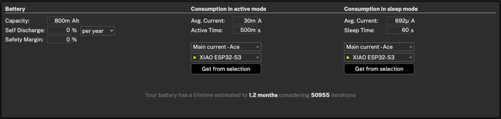
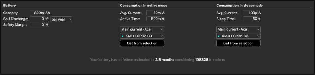
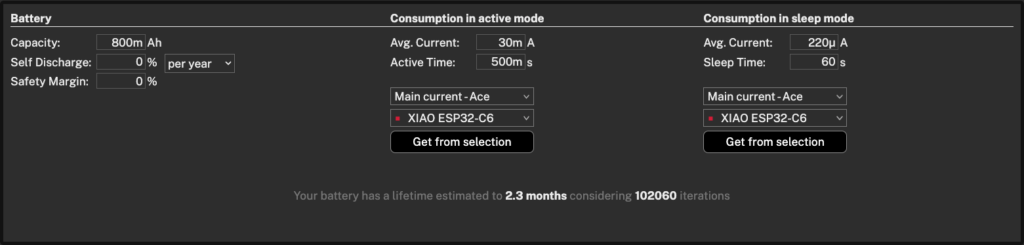
| Board | Lifetime estimation | Iterations |
|---|---|---|
| XIAO ESP32-S3 | 1.2 months | 50,955 |
| XIAO ESP32-C3 | 2.5 months | 108,328 |
| XIAO ESP32-C6 | 2.3 months | 102,060 |
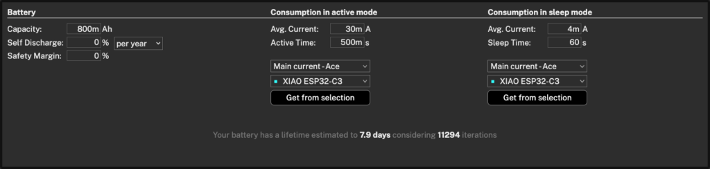
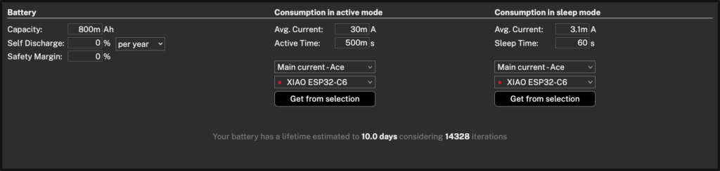
Now consider what happens if you use the Seeed datasheet light-sleep values instead of the validated measurements:
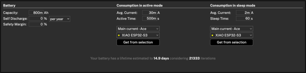
| Board | Lifetime estimation | Iterations |
|---|---|---|
| XIAO ESP32-S3 | 14.9 days | 21,333 |
| XIAO ESP32-C3 | 7.9 days | 11,294 |
| XIAO ESP32-C6 | 10 days | 14,328 |
The gap is substantial. Using the Seeed datasheet value to estimate battery life for a radio-off design would underestimate the actual battery life by a factor of 3 to 21, depending on the board.
| Board | Light-sleep (datasheet) | Light-sleep (measured) | Overestimate factor |
|---|---|---|---|
| XIAO ESP32-S3 | 2 mA | 692 µA | 2.9× |
| XIAO ESP32-C3 | 4 mA | 193 µA | 21× |
| XIAO ESP32-C6 | 3.1 mA | 220 µA | 14× |
These calculations use a fixed average current and a set battery capacity, which works for quick comparisons and sanity checks but is not sufficient for production level estimates. In practice, battery discharge is not linear, voltage cutoffs lower the usable capacity, and temperature affects both the battery and the device itself. To account for these effects, the Otii Battery Life Estimator uses custom battery discharge profiles created for the actual application and consumption profiles of the different activities performed by the system, resulting in much more realistic battery life predictions. More on that in the follow-up article.
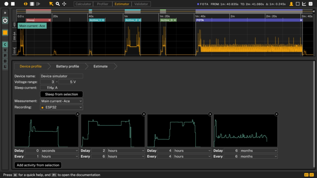
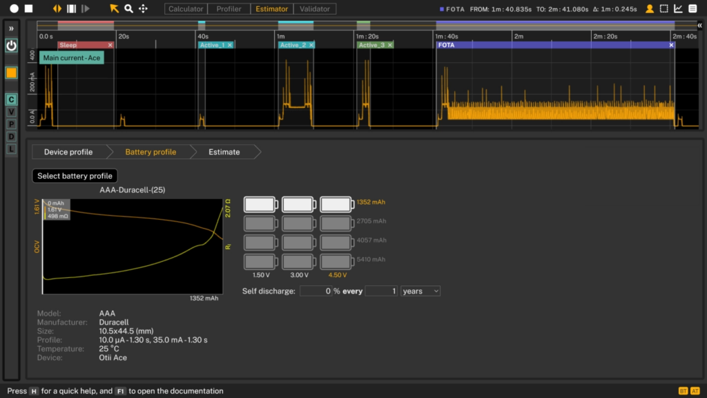

Battery Life Estimator: Device profile, Battery profile, Estimate @ Otii Product Suite
Conclusion
Now you’ve seen how three ESP32 boards actually behave in their deepest sleep — measured against each other, and against the numbers their datasheets promise. The gap between the two is the whole point. A datasheet figure tells you how the silicon behaves in ideal conditions: a reference design, a controlled bench, one specific sleep configuration. Your product runs somewhere else entirely, with its own voltage regulator, firmware settings, and pin states that the datasheet was never measuring.
And this is the quiet part. Deep-sleep current is the most predictable state a board will ever be in, and even here the datasheet is only a starting point. In the next articles we add BLE, Wi-Fi, and Thread on top of this baseline — where duty cycle, protocol timing, and network conditions pull real-world consumption much further from any single quoted number.
Which is why the baseline matters, and why it has to come from your hardware. Measure power on your own board, with your own firmware, under the conditions your product will actually face. Those measurements become a power profile; combine that with a real battery discharge model and you can predict how long your device runs on a given battery with confidence. That’s what lets you size a battery before committing to an enclosure, catch a firmware regression before an OTA reaches the field, and hand your customer a specification you can stand behind.
Skip it, and you’re guessing. In a real product, a bad guess isn’t a quick redesign at the bench — it’s a technician sent to the field, a batch of returns, or customer trust that’s hard to win back.