Measuring LTE power save modes on Nordic’s nRF9151-DK
Measuring LTE power save modes on Nordic’s nRF9151-DK
Cellular IoT standards such as LTE-M and NB-IoT include a set of power-saving features, PSM (Power Saving Mode) and eDRX (extended Discontinuous Reception), designed to reduce current consumption for battery-powered devices. When properly configured, these mechanisms can greatly extend device lifetime in the field. However, trade-offs exist: aggressive power-saving settings may lead to increased latency or reduced responsiveness to downlink messages. As such, understanding the behavior and timing impact of these modes is essential during product development.
Understanding LTE power modes
To evaluate and fine-tune these parameters, developers must be able to control and observe the modem’s behavior in real time. Tools like Otii Arc and Otii Ace allow direct control over the cellular modem via AT commands over UART, while simultaneously measuring current draw. This makes it easy to analyze the energy impact of different configurations and identify optimal settings for the application.
In this study, we showcase how to do precisely that. We’ve selected the Nordic nRF9151-DK connected to the Telia cellular network in Lund, Sweden. It’s essential to note that the availability and behavior of power-saving features are influenced by the network operator and local infrastructure, such as base station configuration, which may limit the options supported or affect their practical performance.
Low power modes in LTE-M and NB-IoT
Short on the LTE power-saving features:
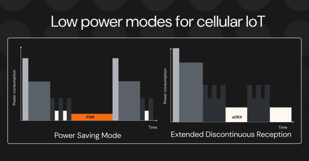
eDRX (Extended Discontinuous Reception) is a power-saving feature in LTE-M and NB-IoT, introduced in 3GPP Release 13 (2015). It reduces energy use by allowing devices to sleep for extended periods, briefly waking up to check for messages. The principle is using scheduled “naps”; hence, instead of constantly listening, the device goes into standby, with the receiver off, staying reachable with some added latency.
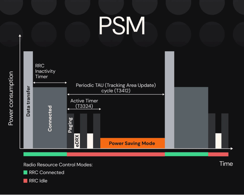
Power Saving Mode (PSM), introduced in 3GPP Release 12 (2015), allows LTE IoT devices to enter a deep sleep without fully disconnecting from the network. Instead of frequently waking to check for network pages, devices negotiate longer sleep intervals where the radio is completely off, waking only to send data or after a set time. Meanwhile, the network is buffering the incoming data.
For a deeper dive into how these features work, check out this article: eDRX and PSM for LTE Low-Power IoT from Ondomondo.
The measurement set-up
The set-up
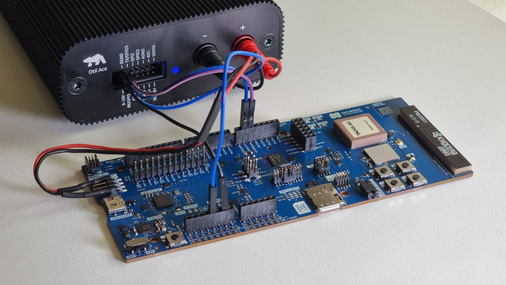
Here is how to connect the Otii Ace and the nRF9151-DK board (the names of the connections are the pins on the Otii Ace):
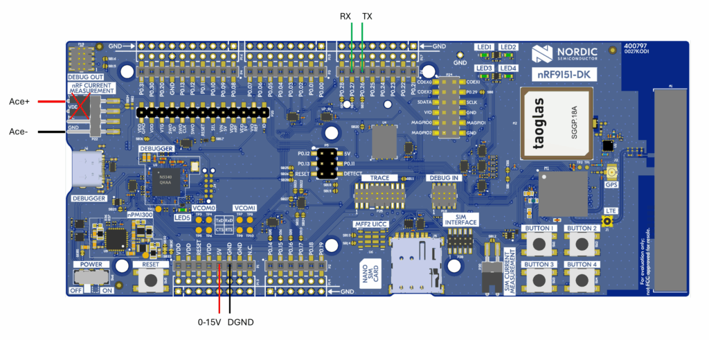
Remove the jumper where Ace+/- is going to be connected. In this setup, Otii Ace’s main channel will power and measure the VDD of the nRF9151-DK, and the 0-15V pin will power everything else on the board. The board can also be powered by using the USB power, but using the 0-15V pin makes it possible to do a power cycle of the board if needed. NOTE! If you choose to power via USB, DO NOT power 0-15V to the 5V pin.
Get started with the nRF9151-DK board
In this study, we have used Nordic’s AT Commands application. Here are the steps to get started:
- Download the nRF Connect application for your desktop
- Go to Quick Start
- Set the name of the board
- Select the AT Commands application and click ‘Program’
- You can disregard the other steps, as they are not crucial for this investigation
- Disconnect the USB cable from the board; in this example, Otii Ace will power it instead.
Note: The AT Commands application utilizes the board solely as a modem, with minimal power-saving features implemented on the board itself. This investigation focuses solely on the effects of different network power-saving features, so the board’s power consumption can be disregarded, as it will not enter a deep sleep state.
nRF9151-DK board supports both LTE-M and NB-IoT.
Get started with Otii Ace Pro
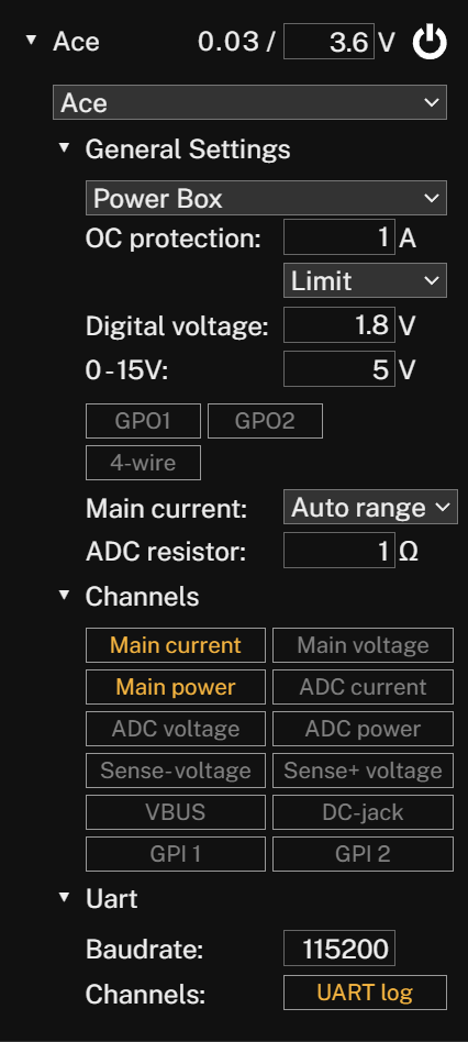
In the Otii desktop application, set the following:
- Main voltage between 3.0 and 5.5V
- Overcurrent 1A
- Digital voltage 1.8V
- 0-15V set to 5V (must not exceed 5.5V) If 0-15V connection is used, USB MUST NOT BE PLUGGED IN!
- Enable
- Main current
- Main voltage
- UART log
- Set Baudrate to 115200
Measuring PSM and eDRX on nRF9151-DK
Setting up the power save features and getting started with the power measurements follows this path:
- Start a recording in the Otii desktop application
- Power on Otii Ace in the app
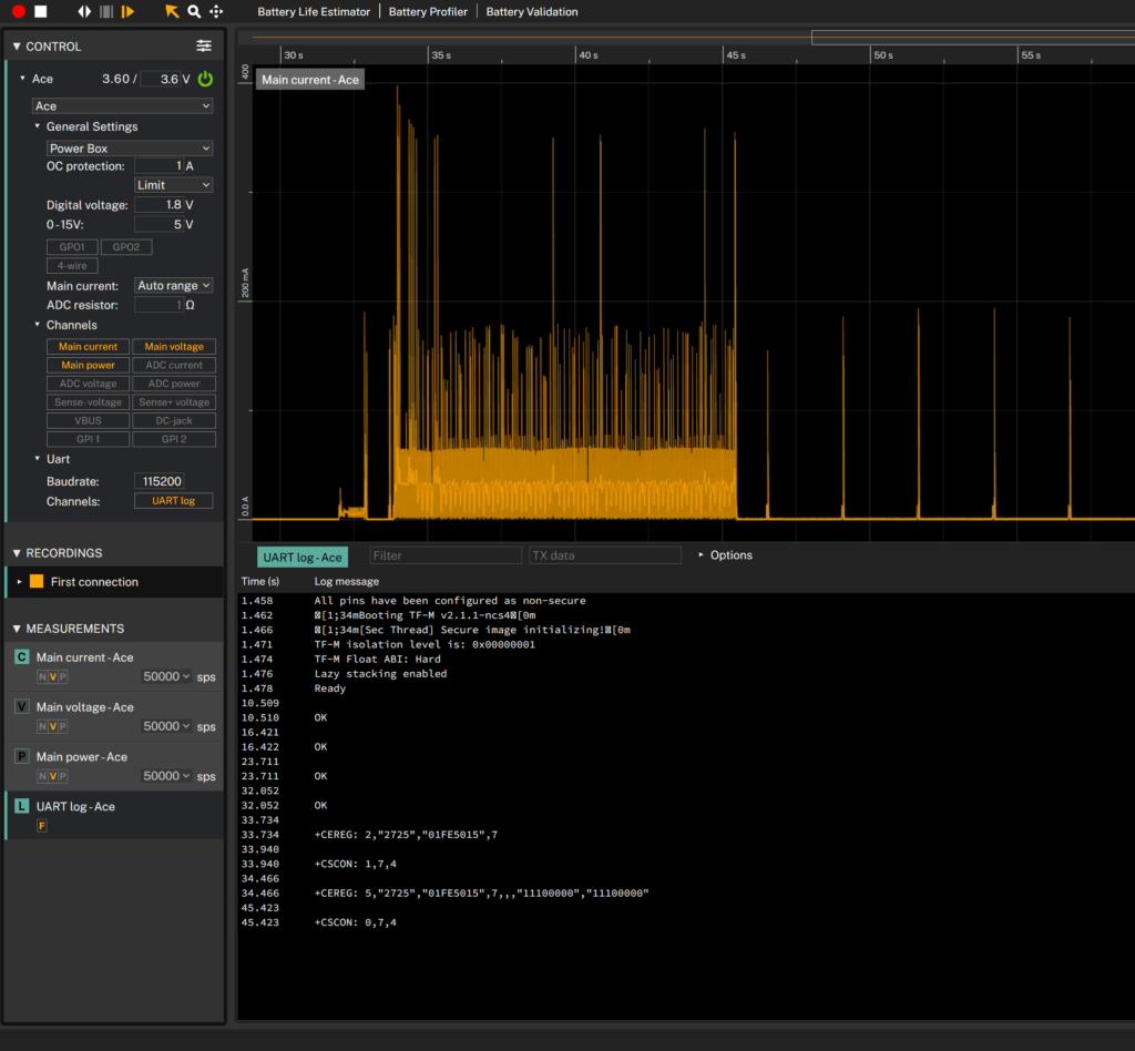
The Nordic nRF9151-DK board will now start. In the UART log in the Otii app, a response of “Ready” will appear when the board is up and running. Once ‘Ready’, the board is in AT command mode, and can be controlled by sending AT commands via the Otii app. When an AT command is accepted, the response will be “OK”. All AT commands can be found here.
The radio is turned off by default when the board is started. To send AT commands, enter the commands in the TX data field above the UART log in the Otii app. The response will be visible in the UART log.
Here is how the AT commands procedure on the nRF9151-DK for LTE-M eDRX power saving mode appears in the UART log of the Otii app, along with the measured power profile.
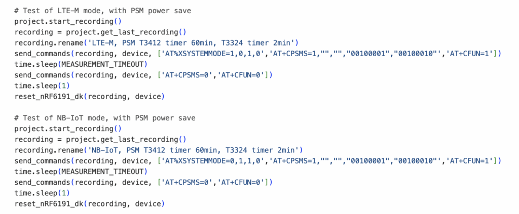
The tests can be performed manually or automated. In this study, we opted for automated tests since the testing involves many possible configurations, and automation makes the process easier. We used Otii Automation Toolbox and a Python script that can be downloaded from Qoitech’s GitHub here.
The configurations that we tested are:
- LTE-M mode, with no power save modes
- LTE-M mode, with eDRX power save
- NB-IoT mode, no power save
- NB-IoT mode, with eDRX power save
- LTE-M mode, with PSM power save
- NB-IoT mode, with PSM power save
- LTE-M mode, with eDRX and PSM power save
- NB-IoT mode, with eDRX and PSM power save
We tested each configuration for 4 hours, recording a total of 32 hours of data. While the duration can be adjusted depending on the amount of data required for comparison, this setup provided a good balance between test depth and overall testing time.
Testing PSM is a bit more challenging, as it heavily depends on the settings allowed by the network provider. In this test, we used the Telia network in Lund, Sweden, where the minimum supported PSM interval is one hour. Some networks also support combining PSM with eDRX, which is a feature that the Telia network allows.
Results
The goal was to demonstrate how to easily analyze the energy impact of different power-saving configurations and identify the optimal settings. Below are the results from our measurements.
Note that a few conditions may affect the results:
- We performed all tests on a live network (Telia, Lund, Sweden), where network behavior may vary beyond our control.
- During testing, we did not transmit any data—the nRF9151-DK functioned solely as a cellular modem. Actual current consumption will vary depending on data volume and transmission frequency.
- Power-saving modes affect modem behavior. If constant message reception is critical, long sleep intervals may not be suitable, requiring a balance between power consumption, responsiveness, and accessibility.
- We did not configure the nRF9151-DK to operate in its lowest power state during testing (we use it out of the box), which resulted in higher sleep current than expected in a real product scenario. The major contributor to this elevated current consumption comes from the UART block in the chipset that consumes around 600uA constantly unless it is turned off. To get the most realistic power figures, the UART block needs to be turned off.
LTE-M power modes
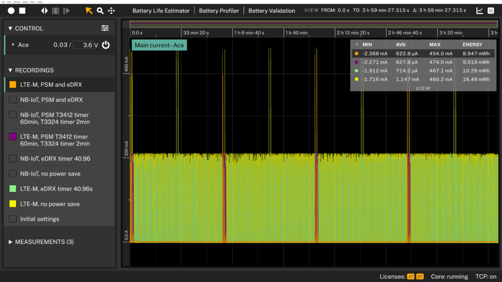
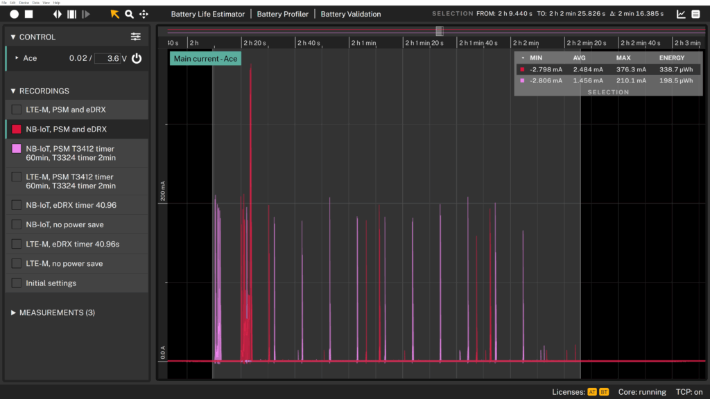
In the top-right corner of the graph, the statistics show the average current consumption over one hour of measurements for various LTE-M configurations, both with and without power-saving modes.
As shown, enabling eDRX significantly reduces power usage from approximately 1.15 mA to approximately 710 µA.
Activating PSM lowers it even further, from ~710 µA to ~630 µA.
We used both eDRX and PSM together and measured the lowest current consumption at approximately 623 µA. The improvement over PSM alone was minimal, but the majority of this current consumption is the UART block that is enabled, consuming roughly 600uA.
NB-IoT power modes
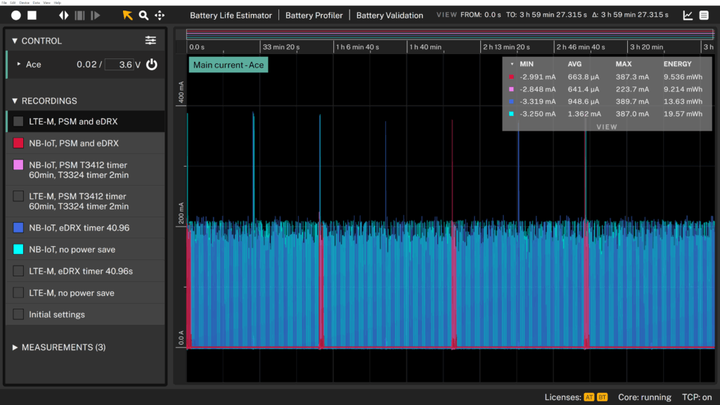
We performed a similar comparison using NB-IoT to observe the step-by-step impact of enabling power-saving modes.
With eDRX enabled, the average current consumption dropped from approximately 1.36 mA to 950 µA. Enabling PSM further reduced the current to around 640 µA, the lowest observed value. Note again, the ~600uA UART consumption.
Interestingly, combining eDRX and PSM resulted in a slight increase to approximately 660 µA. This rise is noticeable when zooming in on the second and third modem wake-up cycles, see the graph below.
We did not further investigate the cause of this behavior. When using PSM and eDRX together, the device first enters eDRX mode, where it sleeps and periodically wakes to check for downlink messages (see image below). After the T3324 Active Timer expires, the device transitions to PSM, a deep sleep state where it becomes unreachable to the network but remains registered. It stays in PSM until the T3412 timer expires (Periodic TAU) or it needs to transmit data. This combination allows a balance between downlink accessibility and maximum power savings. However, not all networks support both modes simultaneously, and improper configuration—such as overly frequent eDRX cycles—can increase power consumption. It’s crucial to test and measure performance in your specific network environment.
Testing and balancing low power modes in LTE-M and NB-IoT
Choosing the proper power-saving mode depends on your use case. Devices like meters or trackers that send data infrequently and don’t require downlink benefit most from PSM, which offers the lowest power consumption. Devices such as alarms or wearables that need occasional downlink access benefit better from eDRX. When combined, eDRX keeps the device reachable before entering deep PSM sleep, but if not tuned correctly, this can increase power consumption. Always test under real network conditions to strike a balance between battery life and responsiveness.
To fine-tune power-saving features like PSM and eDRX, developers need real-time visibility into modem behavior. Tools such as Otii Arc and Otii Ace provide this by enabling AT command control over UART while simultaneously measuring current draw. When automated, this setup allows for easy analysis of the energy impact of different configurations and the identification of the most efficient settings for your specific application.