How does UART communication drain your ultra low-power IoT device?
How does UART communication drain your ultra low-power IoT device?
Remember the time when your computer mouse had this huge chunky connector that you quite literally had to screw into your computer? These were most likely using UARTS to communicate. While thanks to USB, thick cables are clearly a thing of the past, UART for sure isn’t. It is still used in many different electronics like GPS or Bluetooth modules for your Raspberry Pi, Arduino, or other microcontrollers.
Optimizing designs for ultra-low power has become one of the top challenges in battery-driven device development, both on hardware and software levels. We often see discussions around UART communication and how it may or may not have a negative effect on power consumption.
So, does UART communication really drain energy from your ultra-low-power IoT device?
The TL;DR answer is No, it doesn’t – or better it shouldn’t as it really depends on how you use or implement it.
Keep an eye on leakage current
One simple, first step to avoiding unnecessary power drain is to eliminate leaking current from your TX and RX channel. The high leakage might not be too common but better to be safe than sorry. No one is keen on an unpleasant surprise later on.
Write your code mindfully
You might also be thinking about having a #define in your code, that defines when the UART with printouts is enabled or disabled. For example, while developing you want it enabled and in the production software disabled. This is a really good approach, and to convince you, here is a real-life scenario happening too often:
You and your colleagues are working hard on lowering the power consumption. You have continuously measured the current consumption and have seen the progress. During development you have enabled the UART for debug purposes – it’s neither pretty nor optimized, so you have accepted that the current consumption has increased a lot when it is enabled. However, at a later stage, by accident, someone enables the UART in the main branch and that software is flashed, perhaps over the air, into millions of devices. With a simple release, you ended up with many unhappy customers.
To avoid this, make sure that you have a continuous integration setup with current consumption requirements that will spot errors in the software, like enabled UART communications.
Turn everything off
Enabling the UART might turn on the lights for a lot of things in your software – figuratively speaking. There are blocks in the MCU being enabled and clocks turned on. Usually, MCU manufacturers make it as easy as possible for developers to run their code, which means that everything is turned on from the start by default. So, make sure that you disable everything before the MCU enters the sleep mode. Enabled UART clocks might prevent the MCU from going into the deepest sleep and, thus, cause unnecessary current consumption. You want to look into your clock-tree and figure out what your enabled UART really does and turns everything off.
Reality check
Ok, let’s look at two different firmware running on the same device – the only difference is that one of them has UART enabled by a #define and the other doesn’t. We use Otii Arc Pro and measure current consumption for a LoRaWAN device.
The selected part in the first picture, Fig.1, shows the device when it is active and sends UART messages. In the second picture, the selected part shows you the MCU in sleep mode.
The orange recording is with UART enabled and the green recording with UART disabled.
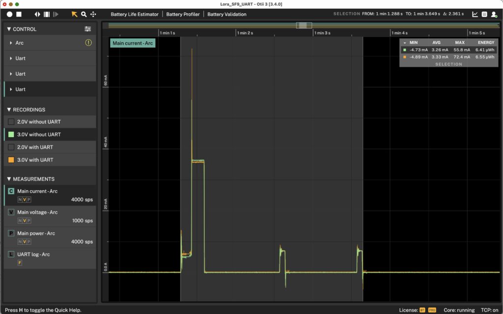
Fig. 1 Active LoRaWAN device with UART communication enabled (orange graph) and disabled (green graph).
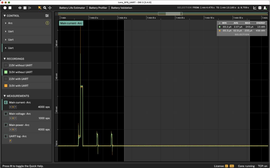
Fig. 2 LoRaWAN device with MCU going to sleep (selected part of the graph) with UART communication enabled (orange graph) and disabled (green graph).
In the active mode, there is a slightly increased average current consumption, from 3.26mA to 3.33mA (see stats in the upper right corner in Fig 1.). Since the duration of the active mode is only about 2sec, the difference is too small to have a real impact on the battery lifetime.
The sleep mode, however, is much more interesting. The difference here went from 2.07uA to 62.9uA (see stats in the upper corner in Fig. 2). Yes, we’re talking uA here but when you start calculating battery life with the long sleep periods that IoT devices have it doesn’t seem too small anymore.
It is clear that this firmware is optimized for having UART disabled.
Estimating the Battery Lifetime
To show you the difference in battery lifetime we calculated battery life with the Battery Life Estimator in Otii. It’s part of the our Otii Pro software.
Let’s assume the device has one active period per hour, meaning it will be active, send data and then sleep for almost 3600 seconds – or 3600 minus the active period to be exact (we used 3600 for simplicity).
Fig. 3 shows the UART disabled and Fig.4 shows the UART enabled.
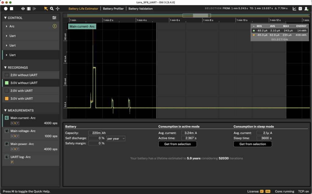
Fig. 3 Battery life estimation with disabled UART communication
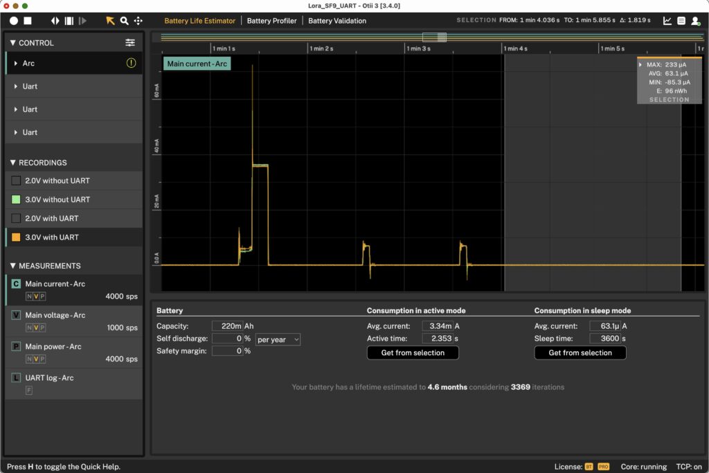
Fig. 4 Battery life estimation with enabled UART communication
These numbers don’t seem that small anymore! It went from 5.9 years estimated battery time down to 4.6 months.
So, the moral of the story – turn off everything that UART enabled. Only then there will be very little power add/on, when the MCU enters sleep mode. Include it in your continuous integration so it becomes a quality check for your releases. If you forget to do this and you by accident release the software with UART turned on, you will most certainly sacrifice a lot of battery life.